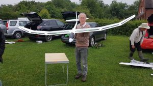
Before the Radion XL settled in to the tree, Dave proudly posed with it.
Before the Radion XL settled in to the tree, Dave proudly posed with it.
At first sight this might look like a portable wind break – but it isn’t!
It’s actually Barry’s new slope project – a big delta winged glider made from sheets of plywood! Ask Barry for details!
Barry flew it for the first time off a bungy (or is that bungee?) at the field last Sunday (14/01/18)
 Barry said after the attempt that the CoG needs adjusting! Good luck Barry!
Let’s hope this is the first of many new projects for 2018!
Slightly late – Happy New Year!
The PSSA organised a mass build this year the subject chosen was the Sky Hawk, last weekend was the day when all of the models were presented and flown.
Steve Bowdler decided that he would like to build one and here are a few photos that were taken at the great day of judging, as you can see the standard was high.

Time for the maiden, Steve told me there was a good blow so plenty of lift available


Steve took his model down to Cornwall with the intension of doing the maiden flight there, but the conditions were just not right for it.
I took the opportunity to photograph it, here are my pictures so you can see Steve`s model in greater detail, I think you will agree it looks smart.


Thanks to Steve for letting us share his photos.
Pike the Slope Soarer
Following the successful maiden flight at Leckhampton yesterday I thought I should take a couple of pictures of it whilst it is unscathed… Pike started out as an experiment to make half a wing using balsa covered foam to compare weights with the glass fibre wings. This showed a 50% reduction in weight for the equivalent wing area in glass fibre. I also wanted a thinner wing section to help with the speed range to the extent that the aileron servos are mounted to the wing core within the fuselage and using a torsion bars. To test the wing I built a crude balsa box fuselage with V tail and painted the whole lot in clear acrylic varnish.
The initial maiden was carried out at the field where it performed in a similar fashion to the Skua being a light wing loading (9.8oz /sq foot). for maiden at Leckhampton, Mel launched it and to my surprise it was easy to fly and more stable that the Skua which maybe due to the bigger wing span, 1.87m against 1.5m for the Skua. The only real problem was the crow braking which caused the nose to climb, more down aileron needed.
What next, slicker stronger wings, sleeker fuselage…


For a while now I have been looking for something to use to hold parts in place during a build.
I have used old batteries, baked bean tins etc in the past, but now I have found these.


They are cast iron each 1lb in weight, they can be stacked if more pressure is needed to hold something.
The cost was £0.30 each, but delivery was over £5.00, so I would suggest that if you want to buy some of these then try and find someone to share the delivery cost, I think you can buy quite a few of them before this cost goes up.
https://www.mightonproducts.com/1lb-stackable-cast-iron-weight-2667
The link above is where to find them, you will need to copy and paste it, I haven`t found how to post a live link.
Mel
I found this.
It comes from this thread.
http://www.rcgroups.com/forums/showthread.php?t=1105190
Since it is an adjustable tow hook, you don’t even have to worry about where it goes as long as you are more or less centered on the CG. That is precisely due to the fact that your cg, and your tow hook location are not actually related. Whereever you put your tow hook becomes the CG during a launch. In other words, even if your tow hook is one inch behind the CG (Say you balanced your Supra at 90mm from the LE, and the suggested location is around 104mm) If you mounted the tow hook at 104, as long as that is not behind the wings center of pressure, you will get a nice clean stable launch. The tow hook location is the CG during launch. Also, true would be if you had an unflyable CG due to all of your nose weight falling out, your launch would still go fine while under tension. As soon as tension is relaxed or released you would have an unflyable or way tail heavy glider on your hands.
So, use the suggested CG as a guide, center your hook box on that point, install, fly, and adjust. Nothing to it.
Good luck
Mike
Following on from the ‘Flying Brick’ lessons learned which is ready for the right conditions i.e. lots of lift… I had a rethink on my second prototype requiring it to be significantly lighter and have a motor fitted (hidden when soaring) to enable it to be flown at the field assuming it does fly.
The key differences to try and meet the lighter weight is; a carbon fibre boom and moving tail as the back end of the Flying Brick is the primary contributor to the overall weight as the balance weight had a ratio of 2.8:1.
To improve the build finish and help keep the weight the wing skins are made as two separate pieces using aluminium moulds then bonded together with spares glued in. The fuselage mould is mage from 2” aluminium tube; shaped then split on the vertical axis.
I have attached a couple of initial photographs; one of the moulds and the other of the part assembled components. I will be providing updates as I get a little further through the build.


We are now getting closer to painting, need to fit the wing servos and tips… The controls for the moving tail and rudder are complete ready to fit after spraying, but what colour(s) shall I use?

The final painting and assembly is complete with an ready to fly weight of 1.4kg a touch heavier than wanted and may push the motor to the limit when field flying, that’s assuming it flies… I used base coat metallic silver as it thin and should be lighter that standard gloss cellulose.

Assuming it flies at the field and is not destroyed, the next step will be to replace the prop spinner with a glass fibre nose for soaring.
A rotary wing aircraft that I can fly outdoors has been something that I’ve been wanting to try for a little while, I even priced up the required items to build a quadcopter on hobbyking, but then procrastinated about buying it until I spoke with Scott who fancied building one too. So I ordered 2 full sets of kit so we could both build one each.
The shopping list I had for each copter was:
1 x Q450 V3 fibre glass frame
1 x Hobbyking multi-rotor controller V3.0
1 x QBrain 4 x 25amp brushless ESC
4 x Turnigy 1000kv D2830-11 brushless motors
1 pack of 4 10×4.5 slow fly props clockwise
1 pack of 4 10×4.5 slow fly props counter clockwise
It all arrived, so I built up the frame putting a drop of thread lock on each of the screws, and attached the 4 motors to the end of each arm, again with thread lock. I connected each motor to the speed controller, and just to check everything worked plugged it into the controller board and receiver and powered up… Nothing happened… So I thought I’d better read the instructions. First the speed controller required calibrating to the radio, setting the top and bottom of the throttle throw. So I did this. The instructions for the hobbyking controller board were ‘sparse’ to say the least, I eventually found by trial and error that setting the throttle to lowest and the rudder full left seemed to initialise the controller board, then every thing sprang to life. I now know this is ‘disarming’ the nav board… As opposed to arming which is done by moving the rudder to the right. Still none the wiser as to what that is if anyone knows?
Of course the first thing I had to sort now was the order of the motors, this was actually in the hobbyking instructions, but the firmware which shipped with the board was for a quad with a motor in front, behind, left and right. I wanted an ‘X’ configuration with a motor front-right, front-left, back-right and back-left. Fortunately I had a USBasp connector to update the firmware on the board, so when I eventually found the firmware update utility I update this to the X configuration from the hobbyking site, change the order of each motor to its connection on the controller board, powered up, put in left rudder to start the board and then a little throttle. This time all the motors appeared to start, and adding aileron and elevator appeared to speed up and slow down the motors as I would expect. All is going well, next was to check the motors are all spinning in the correct direction and with a helpful little image in the instructions this wasn’t too much of an issue by placing a finger on the side of the motor case to see which way my finger was pushed, then reversing 2 wires if it was spinning the wrong way.

So next is attaching all the bits to the frame. Reading advice from other copter builders all seem to say that the controller board needs to be damped from vibration, my setup with the single ESC would seem to be advantageous in this situation since I could attach the controller board to the top of the ESC case using foam tape, then the ESC to the frame using foam tape the weight of the ESC should then help to damp the controller board from the vibrations in the frame. Although the heat management may be affected by attaching this to the ESC. We shall find out the effect soon anyway.
So after tidying up all the cables and tying them down this is what my copter looks like:

At this point I got a little cocky and decided to spin it up with the props attached to see if it will shuffle around the floor in the correct directions, yaw the right way, etc. So I put a little bit of throttle on, not enough to take off, but enough to start taking the weight, then just touched the rudder slightly and the copter launched and smashed into the TV. After I extracted it, I removed all the props again (replaced the broken ones) and turned all the giros to minimum, and reduced the rates on my transmitter to 50% (with the dual rates switch set so I can increase this if needed) and put some expo in too. Strangely the pots on the board seem to need to be turned clockwise to reduce the rates. Turning them this way gave the lowest change in motor speeds for any given input, this way seemed a little counter intuitive to me. But I now felt confident again and being even more careful now I put the props back on and tried again, this time success, although there is a lot of effect from the walls and floor generally it seemed to shuffle in the way I expected.
All put together, this is now how it all looks:

I still need to put a bit of tape on the receiver antennas, but next stop… a field test.
At the field we noticed that the single cable that I’d seen used elsewhere actually cross connected the Ailerons and Elevators, although we had set everything up so that the motors were working correctly of course the controller board didn’t have the motors set up correctly, so the first test flight was extremely unstable, the giros sending the copter more and more out of control. This was corrected, we then needed to add a significant amount of trim on various axis, but after this the copter took off and was controllable, but still a little wobbly. We turned up the gain on the giros on the controller board, this improved stability, this is the resulting flight by Mr Scott:
http://www.youtube.com/watch?v=s-FutairsgQ
I then flew a little higher and further, caught a bit of wind which started it swaying, because it was a bit further away it was difficult to tell which way it was swaying. I should have simply left it to the giros to sort itself out, but instead I lost my cool and knocked the power down which then made things worse and ultimately led to it crashing

But I do take a lot of positives from the days testing. We managed to get some genuine flying time, the copter performed well and we did get a lot of information that we can take forwards and improve them and do better next time. And Scott managed to do all this without smashing his up which is even more of a plus so he can take it forwards without too much work.
Good fun… needs a bit of work 🙂
Update 30/11/2014
I mounted the FPV and OSD removed from the catalina when I updated to the Ardupilot, the following was flown Line Of Site, but recorded from the Ground Station
https://www.youtube.com/watch?v=kcGDjoquTRs
Hi,
I have brought a Chris Foss slope soarer balsa kit known as a “Middle Phase” (advanced version)
I will post photos of each stage of the build process
The kit cost £66 and is good quality, the wings are pre made.
I’m not sure this was what my wife was hoping for when I told her that since the weather forecast wasn’t very good I’d do some decorating this weekend.
![20140427_113037[1]](http://blog.smfc.co.uk/wp-content/uploads/2014/04/20140427_1130371.jpg)
Pingu the pilot in situ 😉
![20140427_113059[1]](http://blog.smfc.co.uk/wp-content/uploads/2014/04/20140427_1130591.jpg)